
Hello everybody.
When I graduated as an architect 25 years ago, my dad gave me a lifeboat. He being an old sailor, thought it to be the perfect gift! It had spent its life in the extreme North Atlantic, sitting on a Russian fish freezer vessel. Originally built in Denmark, it apparently wanted to come home and en route to the scrappers in Bilbao Spain, the ship tore loose from the tug in a storm. The whole menage drifted unto our local shore and my dad salvaged one of the lifeboats.
Fast forward, after actually moving it with me for 25 years to all kinds of locations and career and kids sorted, I finally have the time and some savings to get it done. I want to keep most of the big open cockpit, make a tarp-tent construktion for overnight stays, a kitchen stove box and fit an inboard diesel. This is the perfect gunk hole explorer and the massive Swedish archipelago is not so far from here.
I´ll have to weld up a few cracks and straighten out a couple of dings but there´s no real corrosion to speak of, so hopefully hull integrity is good.It does have some airtanks that might be problematic. Just to make sure, I have made an appointment with a shipyard, thats been building alu boats since the 90íes, mostly military and rescue vessels. They´ll survey it and if they say GO, I´ll probably use their bottom paint program and leave the rest unpainted. Biggest headaches are the fitting of the engine, welding in the stern tube and making a new rudder. But let´s see..
Thank´s for having me, I´ll get around to the stupid questions later.
Best regards
Mads
"27 Lifeboat from Denmark
"27 Lifeboat from Denmark
- Attachments
-
- 2.jpg (97.83 KiB) Viewed 11625 times
-
- 3.JPG (154.42 KiB) Viewed 11625 times
-
- 8.JPG (124.67 KiB) Viewed 11625 times
-
- 7.JPG (161.97 KiB) Viewed 11625 times

Re: "27 Lifeboat from Denmark
Very interesting project. Nice that it's not so big it requires a yard or special equipment to move and work on.

-
kmorin
- Donator 08, 09, 10, 11, 12, 13, 14, 15, 16, 17, 18, 19, 20, 21, 22, 23, 24
- Posts: 1744
- Joined: Mon Aug 18, 2008 1:37 am
- 15
- Location: Kenai, Alaska
Re: "27 Lifeboat from Denmark
Really interesting build commentary in the various photos of the round bilge, double ended hull form. My primary concern for corrosion would in the the buttock line of the air voids (seats) where they met the hull plate.
This would be the low point in a 'sealed' cell.... with HATCHES!!!! so if there is corrosion, I'd guess the majority will be located inside these flotation chambers, at the inner most low point in each compartment?
Cheers,
Kevin Morin
Kenai, AK
This would be the low point in a 'sealed' cell.... with HATCHES!!!! so if there is corrosion, I'd guess the majority will be located inside these flotation chambers, at the inner most low point in each compartment?
Cheers,
Kevin Morin
Kenai, AK
kmorin
Re: "27 Lifeboat from Denmark
Thank you All, for the comments.
I´ll report my findings when we open her up and start the project. Did a quick sketch in my 3D program after an really old handheld drawing/meassurement I did in ´98. My fairing skills are a bit rusty, to say the least..
Best regards
Mads
I´ll report my findings when we open her up and start the project. Did a quick sketch in my 3D program after an really old handheld drawing/meassurement I did in ´98. My fairing skills are a bit rusty, to say the least..
Best regards
Mads
- Attachments
-
- spanterids.jpg (76.25 KiB) Viewed 11466 times
-
kmorin
- Donator 08, 09, 10, 11, 12, 13, 14, 15, 16, 17, 18, 19, 20, 21, 22, 23, 24
- Posts: 1744
- Joined: Mon Aug 18, 2008 1:37 am
- 15
- Location: Kenai, Alaska
Re: "27 Lifeboat from Denmark
Mads, in the early 1900's there were a large number of planked cellulose sail boats, double ended hulls like yours, built in San Francisco for a shore side salmon net fishery in Bristol Bay, Alaska.
These boats were converted from sail only to various power installations in the 40's and onward until they generally fell out of use in the 1960's. In order to convert to power the after hull (stern stem post to keel area; curved in Profile View) was cut out at a waterline for the top intersection and a straight transversal line like a station or body section, about 3'- forward the stern post.
Being wooden and not being able to justify the planking implied- metal (some riveted some welded) hull fittings were developed to bolt to the two edges of the wooden hull planks left.
In Plan View the metal was rounded to a stem line that was where the shafts' stern tube was located- some on centerline others off to one side of the new 'keel/stern post'.
The top of this cut out was more or less flat from side to side- so the two bottom panels had a flat(ish) plate to butt up to simplifying the joint. The shaft log had a wooden cutlass bearing (later a Johnson Rubber phenolic and rubber bearing) in the stern end and a hose mounted stuffing box, shaft seal, forward; all one piece that was welded into the conversion fabrication.
I think that I remember seeing one of these and being curious how the shape was formed? must have been with an English Wheel or planishing hammer as the shape was somewhat compound at the lower most, forward intersection with the existing/remaining planking. However that shape became more or less flat in Section while curving ward to the new stern post in Plan view. The 'conversion' created a 'pocket' for the prop and still had decent water flow to the wheel - of course they only ran a few knots at their best speed.
The engines had to be mounted farther and farther forward to allow the boat to stay 'flat' as she ran- if the engines (almost all gas conversions from automotive versions) were too close to the stern the CG was really upset due to the tapering waterlines in Plan of a double ended hull shape.
It was considered a shoal water boat, even with a wheel, and so the bottom centerline keel was extended aft, below the prop to provide a rudder pintle bearing and someplace to take a grounding and transfer that force upward into the hull but avoiding any contact on the prop. The new power boat style rudder was often a pretty stout round bar to allow the entire hull, w fish to 'tag the beach' in shoals with a little swell running. So the rudder post became a structural column to defend the pintle connected rudder shoe to the boat framing aft the prop. Worked pretty well and is still a design used widely in Alaska inboard commercial boats.
In the lines drawing you show some variations in the Profile view of the lower hull buttock lines? Then again, another set of lines is mainly hollow so maybe those two heavier line sets are external or paint lines, or bilge bumpers?? Not sure I see them in the photos or the model shown? I'd say those 1/3" buttocks were more or less hollow their entire lengths- especially nearest the stem and stern post?
Hope you'll be able to take time to share your project's progress, thanks again for posting.
Cheers,
Kevin Morin
Kenai, AK
kmorin
Re: "27 Lifeboat from Denmark
Kevin! Thank you so much for the in depth analysis and historic parallel. I had to break out the dictionary to make sure I didn´t miss a point.
The walloping buttock lines are just what the computer generated trying to fair the lines from my hand sketches/meassurements. As mentioned earlier, they are more than twenty years old, and probably not as accurate as I thought they would be (old time string and tape). When you say "hollow 1/3" buttocks", do you mean concave? The hull is actually fuller and prettier than what came out of the computer. Boat is 500 km from me, so it´s a bit difficult to verify anything right now. Computer sketching was more an exercise in order to see size and think about engine position, diesel/watertank, storage ect.
I´m stil trying to understand your cut-out recipe for the aft stern. If I understand it right, it sounds like a really good idea if the water flow is being resticted by hull geometry. It could make for a simpler way of positioning and welding in the stern tube,as well. Nesting the prop in a pocket probably would be good if one should come across a nice beach to play tag with..
Initially, I just wanted to stick the prop as far to aft as possible, just clearing the keel but after your post, I tried a smallish cut-out and removed a section of the keel (!) so I don´t know if I´m on the right way. This is by no means a "fair the hull" exercise, more just trying to make a leisure gunk cruiser, but I might as well get the flow as good as possible. And being a complete amateur, as well.. A couple of pics more of the hull attached.
Thanks again for your time.
Mads
- Attachments
-
- cutout1l.jpg (36.16 KiB) Viewed 11331 times
-
- cutout2l.jpg (36.69 KiB) Viewed 11331 times
-
- 4.JPG (139.42 KiB) Viewed 11331 times
-
- 5.jpg (82.32 KiB) Viewed 11331 times
-
kmorin
- Donator 08, 09, 10, 11, 12, 13, 14, 15, 16, 17, 18, 19, 20, 21, 22, 23, 24
- Posts: 1744
- Joined: Mon Aug 18, 2008 1:37 am
- 15
- Location: Kenai, Alaska
Re: "27 Lifeboat from Denmark
mads, always enjoy the design part of discussions here on the AAB.com Forum so its my pleasure to discuss your project's future hull modifications.
The cutout you show, looks like a cylinder intersecting the hull surfaces so there's 'room' for a prop. That idea is essentially 1/2 right in my understanding. The top half of the surface is horizontal or parallel to the waterplane- waterline; and will work fine.
However the vertical surface which results from the cutout being athawrtship will not allow very good flow to the lead surface of the wheel. To accomplish that, you'd probable need to cut the hull farther forward, and then replace the the bottom with curved plates that end in a vertical keel bar. This would allow the water to flow around the hull in a similar shape to the original- as the Plan View waterlines would all have the similar taper- the primary difference being their after intersections at the new stern post would be forward of their current intersections And they would be vertical for the ht of the prop 'pocket' or cutout.
The rudder need not be all the way up the stern post, it can be a typical power boat rudder with a shoulder at the hull to take any grounding from the pintle to the hull in a short vertical column.
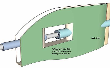
This image is from a similar discussion of a keel however the proportions are wildly different- however I think the idea will come across. In your case the lines of the curved plate keel would likely have to much wider and therefore more curved, and unless you'd use an English Wheel to compound the "boxed keel sides"- you'd have 'plank' the shape that transitions from the curved Body Plan Section(s) to the vertical keel bar shown.
The stern tube shown was from a longer shaft where an intermediate bearing was required- not so in your shorter coupled drive train.
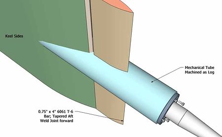
Again, an image from a previous discussion not showing your boat's lines- however the idea is that a mechanical tube would be machined t hold both after cutlass and the forward stuffing box-or shaft seal land- eliminating or vastly reducing the line up issues of welded parts holding a shaft and bearings.
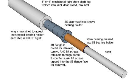
further image from a general discussion of welded aluminum shaft arrangements at the stern bearings. In your case a very short stick out of the shaft tube from the after stern post (stem) would be more applicable as you'd want to keep the wheel as close up to the stern post as possible.
hope these sketches, while not drawn for your hull lines, help make my ideas regarding the shape of the conversion of your hull to a power boat more clear?
Cheers,
Kevin Morin
Kenai, AK
yes, I saw a set of lines (heavier than the rest of the lines) that were 'turned down' at the hull's ends. It was these heavier lines I was remarking about - and they don't show up on the currently posted images. The butt lines in these images turn up as I imagined they would. By 'hollow' I was referring to the turn down lines not those turning up.
The cutout you show, looks like a cylinder intersecting the hull surfaces so there's 'room' for a prop. That idea is essentially 1/2 right in my understanding. The top half of the surface is horizontal or parallel to the waterplane- waterline; and will work fine.
However the vertical surface which results from the cutout being athawrtship will not allow very good flow to the lead surface of the wheel. To accomplish that, you'd probable need to cut the hull farther forward, and then replace the the bottom with curved plates that end in a vertical keel bar. This would allow the water to flow around the hull in a similar shape to the original- as the Plan View waterlines would all have the similar taper- the primary difference being their after intersections at the new stern post would be forward of their current intersections And they would be vertical for the ht of the prop 'pocket' or cutout.
The rudder need not be all the way up the stern post, it can be a typical power boat rudder with a shoulder at the hull to take any grounding from the pintle to the hull in a short vertical column.
This image is from a similar discussion of a keel however the proportions are wildly different- however I think the idea will come across. In your case the lines of the curved plate keel would likely have to much wider and therefore more curved, and unless you'd use an English Wheel to compound the "boxed keel sides"- you'd have 'plank' the shape that transitions from the curved Body Plan Section(s) to the vertical keel bar shown.
The stern tube shown was from a longer shaft where an intermediate bearing was required- not so in your shorter coupled drive train.
Again, an image from a previous discussion not showing your boat's lines- however the idea is that a mechanical tube would be machined t hold both after cutlass and the forward stuffing box-or shaft seal land- eliminating or vastly reducing the line up issues of welded parts holding a shaft and bearings.
further image from a general discussion of welded aluminum shaft arrangements at the stern bearings. In your case a very short stick out of the shaft tube from the after stern post (stem) would be more applicable as you'd want to keep the wheel as close up to the stern post as possible.
hope these sketches, while not drawn for your hull lines, help make my ideas regarding the shape of the conversion of your hull to a power boat more clear?
Cheers,
Kevin Morin
Kenai, AK
kmorin
Re: "27 Lifeboat from Denmark
Little update. Professional alu yacht builder did the survey and it went well, no corrosion to speak off in airtanks or hull. So it´s a GO. Got to see the new alu police boat for Greenland, he was building and made an appointment for off cut material to repair my hull and keel. 3D-Scanning turned out a bit more difficult than first anticipated. So now I´m patching all the scans together to see if there´s a boat in there..
Best regs.
Mads
Best regs.
Mads
- Attachments
-
- IMG_1625.jpg (48.04 KiB) Viewed 10824 times
Re: "27 Lifeboat from Denmark
How's this boat project coming?